Subaru 3AT Governor repair.
Written by Stephen 22,
edited and journalized by Skip
1. Remove the governor cover (3 ten mm head size bolts, for easy reference, bolts will be called by their respective head size). This is to gain access to the governor assembly. This is a very crude drawing of what the cover looks like after removal.
. This cover is located on the pass. side of the differential portion of the transmission. It is just above and behind the axle DOJ unit connection. From “downunder on my turbo car you see this after the cover is removed.
Governor is the devise “bleeding” ATF. Axle stub from diff. unit is in the foreground.
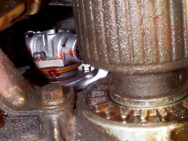
NOTE: On turbo'ed EA-82s, you'll have to take the governor and the bearing plate off as an assembly. This plate is held on with two 8 mm head sized bolts (one can be seen in the above photo, the bolt to the right in the assembly) On non-turbo cars the governor can be withdrawn with out removing bearing plate. As you withdraw the unit it will rotate slightly, there is NO position orientation.
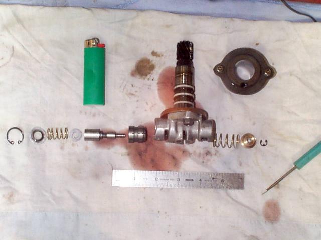
2. Place the governor assembly on a clean surface.
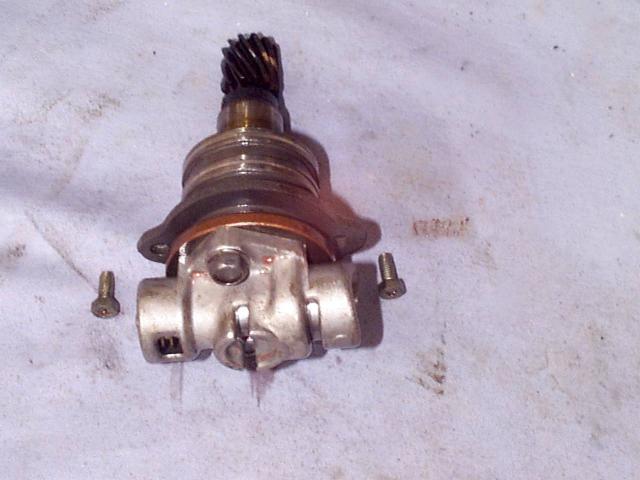
Shown here with the aforementioned bearing plate and it’s retaining bolts.
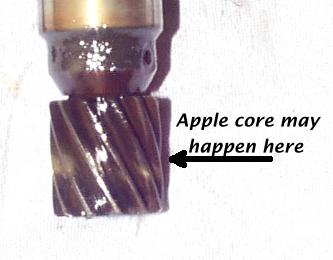
3. Check the governor gears (driving and driven) for apple coring. Apple coring is when the gears are worn in their center section this will need adressed by replacement. They'll look like apple cores if they're bad enough. If only the one on the governor shaft is cored, it's easy to change, but if the internal gear is worn, then you'd have to open the tranny to replace it. A dental mirror can be used to look into the transmission. This gear is still in good shape. Some cars have nylon gears. Turbos are steel.
3. Test the valve action in the governor. There is a spring loaded valve/plunger assembly in the
governor body. Try pressing it down, and see if returns easily to its original position. It
should slide smoothly and return to its original position. If not proceed as follows.
4. Remove the governor valve body from the shaft assembly. (2 bolts). In the above photo they are the two 10 mm bolts still in the unit.
5. Completely disassemble the governor valve body. (be very careful with the snap rings, SAFETY GLASSES ARE RECOMMENDED)
Here it is totally disassembled. Note: keeping pieces laid out in the order they came out is HIGHLY advisable.
As you can see she is going to “bleed” a little, so do NOT do this on Mom’s kitchen table, unless you want sized for a body bag!!
6. Using a suitable method clean all of the internal
components of the valve body. The areas called out in the FSM that need attention are shown here.
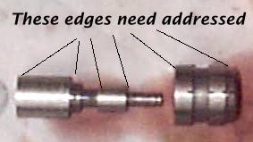
Basicly any
edge that can cause the valve to hang or stick in the body needs attention.
Remove any varnish, and deburr any sharp edges. I used a cordless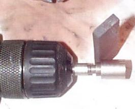 drill and a “honing” stone, commonly used for sharpening knives (Arkansas
stone)
drill and a “honing” stone, commonly used for sharpening knives (Arkansas
stone)
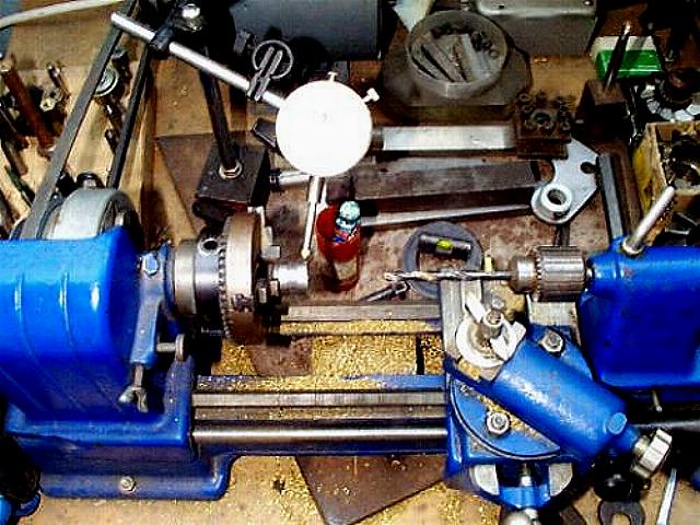
Being very meticulous, and making sure all surfaces are super-clean. Clean everything that will
ever move or see tranny fluid. I also have a small engine lathe that came in handy for the larger sliding unit.
7. Test-fit the valve in the body to make sure it fits well and slides smoothly. If not, deburr a little more until it does. Very improtant to make it slide like a hot knife through butter. If any “catching” is felt the problem will return in a week or so.
8. Reassemble the valve body. Make sure both snap rings are seated in their respective glands. Once it is together, re-test the plunger action. It should be moving like a well-oiled machine.
9. Install the governor assembly back into the tranny, making sure everything is still
clean. If it is, install the cover, a VERY fine layer of RTV silicone can be used on the cover gasket surface if necessary.
10. The job is complete. Test drive and enjoy. This program is not affiliated with any one or thing, and batteries are NOT included.